medical circuit Sensors Detectors Circuits Nextgr Circuit Diagram For the MIC, we use the popular electret MIC, which is the recommended device for all microphone based circuit applications. For the amplifier, we use a standard IC LM386 based amplifier circuit. The entire circuit of the bluetooth stethoscope transmitter circuit is shown below: Parts List Resistors 1/4 watt 5% 4k7 = 1 100 ohm = 1 10 ohm = 1
The circuit diagram of the proposed electronic stethoscope amplifier is designed using two stages, one consisting of the opamp based tone control circuit, and the integrated proper amplifier stage.
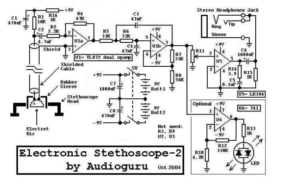
Electronic stethoscope DIY. Circuit Diagram
A medical device called a stethoscope is used to hear sounds made by the body, primarily by the heart or lungs. One of the crucial medical tools that influence remote or self-diagnosis in the medical field is the electronic stethoscope. Hello, My goal is to design electronic stethoscope (the mos simple one) and i have big problem. I was thinking about using about microphone connected to circuit with audio amplifier and on output i have headphones. It's gonna work? and could anyone give some hints how to design this circuit
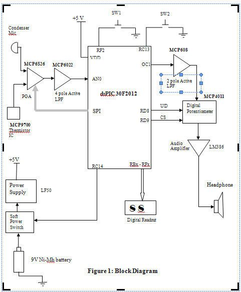
The DIY Wireless Digital Stethoscope project aims to create a modern stethoscope using wireless communication and digital signal processing. This project allows for remote monitoring of heart and lung sounds, offering medical professionals an enhanced tool for diagnosis and patient care. So without further ado let's get started. How Does Wireless Digital Stethoscope Work? Before we go any further in the article, let's discuss how this circuit works. In order to get the heartbeat data, we will first get a stethoscope and cut it in half to fit a condenser microphone, so that we could get the heartbeat sound from the stethoscope.

Digital Stethoscope Circuit Diagram
In this video you have seen about the digital stethoscope and how to build your own digital stethoscope.And I also explained what are the components required